9.3 - Air Moisture and Purge Units
Module: Type III Low-Pressure Appliances
Technical and examination-topic verification date: August 13, 2026
Primary basis: Current EPA Section 608 Type III test topics, current Section 608 venting requirements, and classic Type III exam-preparation concepts
Course role: Explains why air and moisture enter low-pressure chillers, how noncondensables affect operation, how a purge unit separates and removes them while retaining refrigerant, and how purge behavior can reveal system leaks or tube problems
Learning Objectives
After completing this section, a student should be able to:
- Explain why air and moisture can enter a low-pressure chiller while portions of the refrigerant circuit are below atmospheric pressure.
- Define noncondensables and explain why air in the refrigerant circuit creates operating problems.
- Explain why noncondensables tend to collect in the condenser / high-side region of a low-pressure centrifugal chiller.
- State the primary purpose of a purge unit.
- Describe the basic purge-unit process: withdraw a refrigerant/noncondensable mixture, condense and retain refrigerant, remove noncondensables, and return retained refrigerant to the chiller.
- Explain why modern purge operation must minimize refrigerant release and why intentional refrigerant venting is not the purpose of the purge unit.
- Recognize frequent or excessive purging as a possible indication that air is entering through a leak.
- Explain why high discharge/head pressure can indicate noncondensables in the system.
- Explain why excessive moisture collected by the purge system can indicate water-side tube leakage.
- Distinguish normal purge activity from evidence that the chiller itself requires leak investigation and repair.
Introduction
Section 9.1 established the fundamental Type III pressure relationship:
Pinside < Patmosphere
→ air + moisture can leak IN
This is one of the defining service characteristics of a low-pressure chiller.
If the refrigerant circuit were perfectly sealed, only refrigerant would circulate inside it. In the real world, a leak in a subatmospheric portion can allow atmospheric air to enter.
Atmospheric air brings two important contaminants:
AIR GASES
→ mainly noncondensables in the refrigerant system
and:
WATER VAPOR
→ moisture contamination
Unlike a high-pressure leak that is often noticed because refrigerant escapes outward, a low-pressure leak can remain hidden while the chiller continuously draws contaminants inward.
The purge unit exists because these contaminants cannot simply be allowed to accumulate.
The central Type III exam relationship is:
Low-pressure chillers operate below atmospheric pressure
→ require a purge unit
→ primary purpose is removal of noncondensables
Several related Type III diagnostic relationships are:
Frequent purging
→ possible air leak into the system
High discharge pressure
→ possible air / noncondensables
Excessive moisture collected in purge unit
→ possible tube leakage
This section explains why each relationship makes physical sense.
Key Concepts
1. Air Infiltration
When a portion of the chiller operates below atmospheric pressure:
Atmospheric pressure > internal chiller pressure
If a leak path exists:
outside air
→ leak opening
→ refrigerant circuit
The air does not need to be “sucked” by a separate pump. The pressure difference itself drives inward flow.
Common potential air-entry locations can include, depending on chiller design:
- Gaskets.
- Flanged joints.
- Service valves.
- Valve stems.
- Charging connections.
- Purge-system connections.
- Compressor shaft seal on an open-drive machine.
- Other seals or fittings exposed to subatmospheric refrigerant pressure.
Detailed leak-location methods are reserved for Section 9.4.
High-Priority Type III Rule
Subatmospheric chiller + leak
→ AIR CAN ENTER
Do not assume that the absence of an outward refrigerant leak means the refrigerant circuit is tight.
2. Moisture Infiltration
Atmospheric air normally contains water vapor.
Therefore:
Air leaks in
→ water vapor can enter with it
The water vapor can then:
- Remain as vapor.
- Condense on cooler internal surfaces.
- Be absorbed into oil or other system materials.
- Collect in purge-related equipment.
- Participate in chemical contamination or corrosion mechanisms.
The key teaching relationship is:
AIR INFILTRATION
→ usually also a MOISTURE concern
The two contaminants are related, but they are not the same thing.
3. What Is a Noncondensable?
A noncondensable is a gas that does not condense at the normal condenser temperature and pressure at which the refrigerant is condensing.
In a low-pressure chiller, atmospheric air entering through a leak is the classic source.
While refrigerant vapor condenses in the condenser:
REFRIGERANT VAPOR
→ rejects heat
→ becomes liquid refrigerant
air gases remain largely in the gas phase:
AIR / NONCONDENSABLES
→ remain gaseous
→ accumulate if not removed
This is why the system requires a purge mechanism.
4. Why Noncondensables Tend to Collect in the Condenser Region
In the simplified Type III exam model, a traditional centrifugal-chiller purge unit draws the refrigerant/noncondensable mixture through a connection in the condenser region, commonly described as the top of the condenser.
The physical reason is important.
In the condenser:
- Refrigerant vapor enters.
- Heat is removed.
- Refrigerant condenses to liquid.
- Noncondensable gases remain as gases.
- The gases tend to accumulate in regions selected by the chiller manufacturer for purging, commonly near the condenser/high-side collection area.
Thus, a simplified examination model is:
Refrigerant + air enter condenser region
↓
Refrigerant condenses
↓
Air does not condense
↓
Noncondensables collect
↓
Purge unit removes them
The exact physical purge pickup point is manufacturer-specific, but the top-of-condenser relationship is a classic Type III exam cue.
5. Why Noncondensables Increase Head / Discharge Pressure
A clean condenser contains primarily refrigerant vapor and liquid.
At a given refrigerant condensing temperature, refrigerant saturation pressure accounts for the refrigerant portion of the pressure.
When noncondensable gas is added, it contributes additional partial pressure.
Conceptually:
Measured condenser pressure
≈ refrigerant vapor contribution
+ noncondensable-gas contribution
Therefore:
Air / noncondensables accumulate
→ condenser pressure can rise
→ compressor discharge/head pressure can rise
This can lead to:
- Higher compressor work.
- Higher compressor discharge pressure.
- Reduced operating efficiency.
- Higher energy consumption.
- Possible high-pressure safety response if severe.
Exam Relationship
Unexpected HIGH HEAD / DISCHARGE PRESSURE
→ consider AIR / NONCONDENSABLES
But do not reverse the statement into:
High head pressure
→ proves air is present
Other causes of high head pressure can include:
- Inadequate condenser-water flow.
- High condenser-water temperature.
- Fouled condenser tubes.
- Other flow or operating problems.
The exam concept is that air is an important possible cause, not the only cause.
Purge-Unit Purpose
1. Primary Purpose
The primary purpose of the purge unit is to:
REMOVE NONCONDENSABLES FROM THE SYSTEM
That is the key Type III exam answer.
A purge unit is not primarily used to:
- Recover the main refrigerant charge during appliance service.
- Meter refrigerant to the evaporator.
- Control chilled-water temperature.
- Lubricate the compressor.
- Raise condenser-water pressure.
- Repair the leak that allowed air into the machine.
2. A Purge Unit Must Minimize Refrigerant Loss
The gas collected from the condenser region is not pure air.
It can contain:
AIR / NONCONDENSABLES
+
REFRIGERANT VAPOR
If that mixture were simply discharged, refrigerant would be lost.
Therefore, a high-efficiency purge process is designed to:
separate as much refrigerant as practical
from the noncondensable stream
before the noncondensable gas is removed.
High-efficiency purge equipment is designed to minimize the refrigerant carried out with the noncondensable discharge.
Current Section 608 rules prohibit intentional venting of regulated refrigerants and non-exempt substitutes during service. The purge unit therefore must not be understood as a device whose purpose is to deliberately vent refrigerant.
Basic Purge-Unit Process
1. Step 1 — Withdraw the Mixture
A purge connection draws a mixture from a noncondensable collection region, commonly associated with the upper condenser area:
CONDENSER COLLECTION REGION
↓
refrigerant vapor + air/noncondensables
↓
PURGE UNIT
2. Step 2 — Cool the Mixture
The purge unit cools the incoming mixture.
As temperature decreases:
REFRIGERANT VAPOR
→ condenses more readily
while:
AIR / NONCONDENSABLES
→ remain gaseous
This difference allows separation.
3. Step 3 — Retain / Recover Refrigerant
Condensed refrigerant is retained rather than intentionally discharged with the air stream.
Depending on chiller design, the retained refrigerant is returned to an appropriate part of the chiller.
One traditional exam-preparation flow is:
taking suction from top of condenser
→ separating air/noncondensables
→ returning refrigerant to evaporator
This is a valuable exam-preparation flow relationship.
4. Step 4 — Remove Noncondensables
After refrigerant separation:
remaining air / noncondensables
→ removed through the purge process
The exact purge discharge hardware and controls are manufacturer-specific.
The technician must not bypass the purge separation process merely to remove air faster.
5. Simplified Purge Flow
Memorize the process as:
TOP / HIGH REGION OF CONDENSER
↓
REFRIGERANT VAPOR + NONCONDENSABLES
↓
PURGE UNIT COOLS MIXTURE
↓
REFRIGERANT CONDENSES
↓
REFRIGERANT RETAINED / RETURNED
+
NONCONDENSABLES REMOVED
Purge Unit Versus Recovery Machine
Students sometimes confuse these two devices.
| Device | Main Job | When Used |
|---|---|---|
| Purge unit | Removes accumulated noncondensables from an operating or serviced low-pressure chiller while retaining refrigerant | Chiller noncondensable control |
| Recovery machine | Removes refrigerant from an appliance into an external recovery container | Service, repair, or disposal |
A purge unit is therefore not simply a small recovery machine used for the entire chiller charge.
A recovery machine is not a substitute for the chiller’s normal purge system.
Frequent Purging as a Leak Indicator
1. Why Purge Frequency Matters
A properly sealed low-pressure chiller should not continuously ingest large amounts of atmospheric air.
If the purge unit must operate much more frequently than normal:
more noncondensables are entering or accumulating
which suggests:
possible AIR LEAK into chiller
Frequent purging and subsequent refrigerant loss can indicate that a leak is allowing air into the system.
2. Purge Unit Treats the Symptom
This distinction is critical:
LEAK
→ admits air
→ purge removes air
The purge removes the resulting noncondensables but does not close the leak path.
Therefore:
Frequent purging
→ do not just accept increased purge operation
→ investigate leak source
3. Do Not Use One Universal Purge-Cycle Number
The project does not define a universal acceptable number of purge cycles per hour or day because purge behavior depends on:
- Chiller design.
- Purge technology.
- Refrigerant.
- Operating conditions.
- Machine size.
- Manufacturer controls.
The correct exam concept is qualitative:
ABNORMALLY FREQUENT PURGING
→ LEAK INDICATOR
not a universal numerical threshold.
Refrigerant Loss From Purge Operation
1. Why Refrigerant Can Appear in the Purge Stream
The mixture entering the purge contains refrigerant vapor as well as air.
Separation is highly effective but not conceptually perfect in every real operating condition.
Therefore, poor purge performance or excessive purge operation can increase refrigerant loss.
The diagnostic relationship is:
frequent purging
+
subsequent refrigerant loss
→ possible leak allowing air into system
The leak creates the need for more purging, and more purging can increase the amount of refrigerant handled by the purge system.
2. Section 608 Venting Principle
Current Section 608 prohibits intentional release of covered refrigerants during maintenance, service, repair, or disposal except for specifically allowed releases such as de minimis quantities associated with good-faith recovery/service activities.
Therefore:
PURGE
→ separate / retain refrigerant
→ remove noncondensables
not:
PURGE
→ intentionally vent refrigerant
Technicians must maintain and operate purge equipment according to the chiller manufacturer’s procedure and applicable refrigerant-management rules.
Moisture in the Purge Unit
1. Air Infiltration Can Bring Some Moisture
Because air contains water vapor, some moisture may enter through ordinary air leaks.
Thus:
air leak
→ moisture can enter
2. Excessive Moisture Can Point to a More Serious Water Leak
A classic Type III diagnostic clue is:
EXCESSIVE MOISTURE COLLECTION IN PURGE UNIT
→ POSSIBLE TUBE LEAKAGE
Why?
A low-pressure chiller commonly uses shell-and-tube heat exchangers:
water inside tubes
and:
refrigerant on shell side
If a tube develops a leak while refrigerant-side pressure is below the water-side pressure:
water
→ damaged tube
→ refrigerant circuit
That introduces far more water than ordinary atmospheric humidity might.
3. Where Tube Leakage Can Occur
Depending on chiller construction, possible water-to-refrigerant leakage can involve:
- Evaporator tubes.
- Condenser tubes.
- Tube-to-tube-sheet joints.
- Other water/refrigerant heat-exchanger boundaries.
The purge system may then encounter unusually large moisture loads.
4. Excessive Moisture Is a Clue, Not Final Proof
Do not interpret:
moisture in purge
→ definitely one specific tube is leaking
Instead:
EXCESSIVE moisture
→ investigate possible water-side tube leakage
The detailed water-box and tube-leak testing procedures belong in Section 9.4.
Tube Leakage and Pressure Direction
1. Why Water Can Enter the Refrigerant Side
Water circuits can operate at positive pressure while the refrigerant side of a low-pressure evaporator is subatmospheric.
If a tube wall fails:
Pwater > Prefrigerant
then:
water can enter refrigerant circuit
This can create serious problems:
- Large moisture contamination.
- Corrosion.
- Increased purge moisture collection.
- Recovery complications.
- Freeze risk during deep evacuation/recovery.
2. Why Tube Leakage Matters Later in Recovery
If water has entered the refrigerant circuit and the technician pulls a deep vacuum, the saturation temperature of water decreases.
Water can freeze and interfere with recovery or damage tubes/components.
That issue is important enough to receive its own treatment in Section 9.6.
For this section, remember only:
EXCESSIVE PURGE MOISTURE
→ SUSPECT TUBE / WATER-SIDE LEAKAGE
Diagnostic Relationships
1. Air Leak Pattern
Chiller below atmospheric pressure
↓
Air enters through leak
↓
Noncondensables collect
↓
Purge operates more frequently
↓
Head / discharge pressure may increase
↓
Leak investigation required
2. Water / Tube Leak Pattern
Water-side tube or boundary leak
↓
Water enters refrigerant circuit
↓
Excessive moisture contamination
↓
Purge collects unusual moisture
↓
Investigate tube / water-side leakage
3. Normal Purge Versus Abnormal Purge
| Observation | Possible Meaning |
|---|---|
| Occasional purge activity consistent with manufacturer operation | Normal noncondensable management |
| Purge begins running much more often than previous baseline | Possible increased air infiltration |
| Refrigerant loss accompanies excessive purge operation | Possible air leak plus excessive purge handling |
| Unexpectedly high head/discharge pressure | Possible noncondensables; also check condenser-side operating causes |
| Excessive moisture collected by purge | Possible tube/water-side leakage |
No single symptom should replace proper diagnosis.
Purge-System Service Principles
1. Follow Manufacturer Procedure
Purge designs vary significantly.
Different chillers may use:
- Dedicated refrigeration-type purge units.
- High-efficiency purge assemblies.
- Automatic purge controls.
- Purge tanks/reservoirs.
- Refrigerant-return arrangements.
- Different noncondensable detection strategies.
Therefore, field service must follow:
- Chiller service manual.
- Purge-unit manual.
- Refrigerant compatibility requirements.
- Applicable Section 608 requirements.
2. Do Not Disable the Purge Unit to Hide a Leak Symptom
If purge activity is excessive, the solution is not to disable the purge.
That would allow noncondensables to accumulate and can worsen system performance.
The proper logic is:
Maintain purge function
+
Find and correct source of air/moisture entry
3. Do Not Purge Refrigerant Directly to Atmosphere
A technician must not intentionally bypass refrigerant-retention/recovery features and vent refrigerant merely to remove air.
The required concept is:
separate refrigerant from noncondensables
not:
vent the mixture
4. Purge Maintenance Can Affect Chiller Performance
A malfunctioning purge can cause two opposite problems:
- Insufficient purging: noncondensables remain in system.
- Poor refrigerant separation / excessive purge loss: too much refrigerant can be lost with the purge stream.
Thus, proper purge operation requires both:
effective noncondensable removal
and:
refrigerant conservation
Important Terms
Air Infiltration
Air infiltration is the entry of atmospheric air into a refrigeration system through a leak when local system pressure is below atmospheric pressure.
Condenser Head Pressure
Condenser head pressure is the higher refrigerant-side pressure associated with the condenser/compressor discharge region. Noncondensable gases can add to the measured pressure and increase the required compressor pressure rise.
Noncondensable
A noncondensable is a gas that does not condense under the conditions at which the refrigerant is condensing. Air entering a low-pressure chiller is the classic Type III example.
Purge Unit
A purge unit is equipment used on applicable low-pressure chillers to remove noncondensable gases from the refrigerant system while retaining/recovering as much refrigerant as practical.
Purge Discharge
Purge discharge is the gas stream leaving the noncondensable-removal portion of the purge process after refrigerant separation. It should not be understood as an intentional refrigerant-venting stream.
Tube Leak
A tube leak is a failure of a heat-exchanger tube or tube joint that allows communication between the water side and refrigerant side of a chiller.
Water Vapor
Water vapor is gaseous water contained in air. It can enter a subatmospheric chiller with infiltrating air and become a source of moisture contamination.
Figures and Diagrams
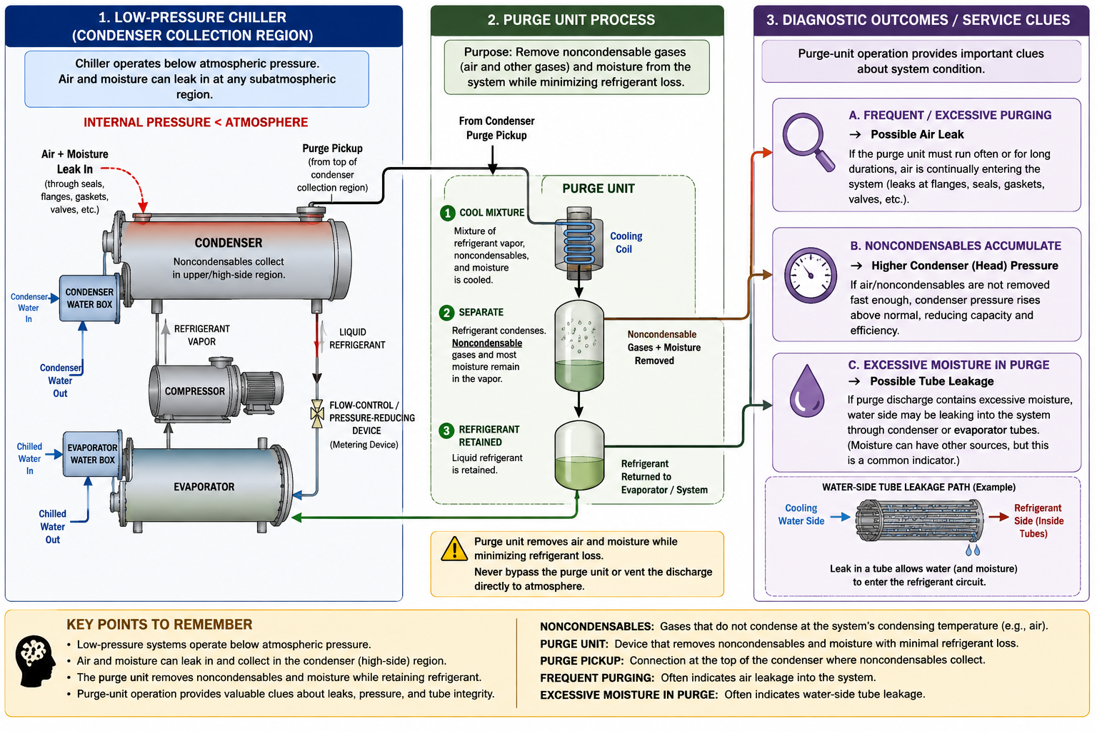
Figure 9.3.1 - Low-pressure purge-unit process and the Type III diagnostic relationships among air infiltration, noncondensables, purge activity, high head pressure, and moisture from possible tube leakage.
AI-generated instructional figure: It may contain visual inaccuracies. Use the accompanying lesson text and cited authoritative sources to verify technical and regulatory details.
EPA 608 Exam Focus
What Students Must Remember
- Low-pressure chillers can operate below atmospheric pressure.
- A leak under subatmospheric conditions can draw air and moisture into the system.
- Air in the refrigerant circuit becomes a source of noncondensables.
- The primary purpose of the purge unit is to remove noncondensables.
- The traditional Type III exam model places the purge pickup at the top of the condenser / noncondensable collection region.
- A purge mixture contains both refrigerant vapor and noncondensables.
- The purge unit cools/separates the mixture so refrigerant can be retained or returned while noncondensables are removed.
- Purge operation should minimize refrigerant loss; intentional refrigerant venting is not the purpose of the purge.
- Frequent or excessive purging can indicate that a leak is allowing air into the system.
- Noncondensables can cause higher condenser/head/discharge pressure.
- High head pressure can have other causes, so it is a clue rather than proof of air.
- Excessive moisture collected in the purge unit can indicate water-side tube leakage.
- A purge unit removes the symptom—noncondensables—but does not repair the leak that admitted them.
High-Priority Relationships
LOW-PRESSURE LEAK
→ AIR + MOISTURE IN
AIR IN SYSTEM
→ NONCONDENSABLES
→ PURGE UNIT
PURGE UNIT
→ retains / returns refrigerant
→ removes noncondensables
FREQUENT PURGING
→ POSSIBLE AIR LEAK
NONCONDENSABLES
→ POSSIBLE HIGH HEAD PRESSURE
EXCESSIVE PURGE MOISTURE
→ POSSIBLE TUBE LEAK
Typical Exam Question Patterns
Students may be asked to:
- Identify the primary purpose of a purge unit.
- Identify the purge pickup location as the upper/top condenser region in the traditional Type III model.
- Explain why air enters a low-pressure chiller.
- Recognize noncondensables as a source of high head pressure.
- Interpret frequent purge operation as a possible leak indicator.
- Recognize excessive moisture in the purge as a possible tube-leak clue.
- Explain why refrigerant is separated before noncondensable gas is removed.
- Distinguish a purge unit from a recovery machine.
- Recognize that purging does not repair the underlying leak.
High-Risk Words
Pay particular attention to:
- Air
- Moisture
- Noncondensable
- Purge
- Top of condenser
- Frequent
- Excessive
- Head pressure
- Tube leakage
- Return refrigerant
- Venting
Common Mistakes and Confusing Points
Mistake 1: Thinking the Purge Unit Removes Refrigerant From the Entire Chiller
That is the job of recovery equipment during service.
The purge unit removes noncondensables from the chiller while retaining refrigerant.
Mistake 2: Saying the Purge Unit’s Main Purpose Is Moisture Removal
The primary exam answer is:
REMOVE NONCONDENSABLES
Moisture can also be handled/collected in purge-related equipment, but that is not the principal Type III definition of purge purpose.
Mistake 3: Assuming the Purge Unit Repairs Leaks
It does not.
It removes air/noncondensables that entered because of leaks.
Mistake 4: Treating Frequent Purge Operation as Normal Without Investigation
An abnormal increase in purge activity is a classic clue for air infiltration.
Mistake 5: Assuming Any High Head Pressure Proves Air Is Present
Air/noncondensables are one possible cause.
Water-flow, water-temperature, fouling, and other condenser problems can also raise pressure.
Mistake 6: Assuming Any Moisture in the Purge Proves Tube Leakage
Atmospheric air already contains water vapor.
The classic tube-leak clue is excessive moisture collection.
Mistake 7: Confusing Atmospheric Air Leakage With Water-Side Tube Leakage
These are two different contamination paths:
Atmospheric leak
→ air + humidity
Tube leak
→ liquid water / major moisture source
Mistake 8: Showing the Purge Pickup From the Evaporator Liquid Pool
The traditional Type III model places purge suction at the upper condenser / noncondensable collection region.
Mistake 9: Treating Purge Discharge as Permission to Vent Refrigerant
The purge is designed to separate and retain refrigerant while removing noncondensables.
Mistake 10: Inventing One Universal Purge Frequency
Purge frequency is manufacturer- and operating-condition dependent.
The exam relationship is qualitative: abnormally frequent purging suggests leakage.
Concept-Check Questions
Question 9.3-1
What is the primary purpose of a purge unit on a low-pressure centrifugal chiller?
A. Remove noncondensable gases from the refrigerant system
B. Increase the chilled-water flow rate
C. Raise the compressor discharge pressure
D. Replace the refrigerant recovery machine during major service
Question 9.3-2
Why can atmospheric air enter a low-pressure chiller through a leak while the chiller is operating below atmospheric pressure?
A. Refrigerant chemically attracts oxygen.
B. Atmospheric pressure is greater than the local internal refrigerant pressure.
C. The purge unit pumps outdoor air into the chiller.
D. Condenser water always flows into the refrigerant circuit.
Question 9.3-3
In the traditional Type III purge-system model, from what general location does the purge unit take the refrigerant/noncondensable mixture?
A. Bottom of the evaporator liquid pool
B. Top / upper region of the condenser
C. Chilled-water pump suction
D. Oil drain connection only
Question 9.3-4
A low-pressure chiller’s purge unit begins operating much more frequently than normal. What should the technician suspect?
A. Air may be entering the chiller through a leak.
B. The evaporator must be overcharged with chilled water.
C. The chiller has automatically changed to Type II.
D. Frequent purging proves that no leak exists.
Question 9.3-5
Why can accumulated noncondensables cause an abnormally high condenser/head pressure?
A. They contribute additional gas pressure in the condenser region.
B. They automatically lower condenser-water temperature.
C. They convert liquid refrigerant into compressor oil.
D. They reduce atmospheric pressure around the chiller.
Question 9.3-6
What is the purge unit intended to do with refrigerant vapor contained in the purge mixture?
A. Intentionally vent all refrigerant with the air.
B. Condense/retain as much refrigerant as practical and return it to the chiller while removing noncondensables.
C. Convert the refrigerant permanently into a noncondensable gas.
D. Send the refrigerant into the condenser-water circuit.
Question 9.3-7
A purge unit begins collecting an unusually large amount of moisture. Which condition should be investigated?
A. A possible water-side heat-exchanger tube leak
B. An open compressor discharge valve
C. A refrigerant cylinder that is too cold
D. A Type I small-appliance restriction
Question 9.3-8
Which statement best describes the relationship between a purge unit and a system leak?
A. The purge unit repairs the leak by removing air.
B. The purge unit removes noncondensables, but the leak allowing air or moisture to enter still must be located and corrected.
C. A purge unit makes leak repair unnecessary on all low-pressure chillers.
D. Purge operation can only occur after all refrigerant has been recovered.
Answers and detailed explanations will be provided in
9.15 - Answers and Explanations.md.
Section Summary
A low-pressure chiller can operate below atmospheric pressure, so a leak can allow:
AIR + MOISTURE
→ INTO THE REFRIGERANT CIRCUIT
Air becomes a source of noncondensable gases.
As refrigerant condenses in the condenser, the noncondensables remain gaseous and tend to accumulate in the designated condenser/high-side collection region.
The purge-unit process can be summarized as:
refrigerant vapor + noncondensables
→ PURGE UNIT
→ cool mixture
→ condense / retain refrigerant
→ return refrigerant to chiller
→ remove noncondensables
The most important Type III diagnostic relationships are:
FREQUENT PURGING
→ possible AIR LEAK
NONCONDENSABLES
→ possible HIGH HEAD PRESSURE
EXCESSIVE MOISTURE IN PURGE
→ possible TUBE LEAK
A purge unit controls the contamination produced by air infiltration, but it does not repair the leak that allowed the contamination to enter.
The next section addresses how a technician safely locates low-pressure leaks and temporarily raises chiller pressure when appropriate:
Section 9.4 - Low-Pressure Leak Detection and Pressurization.
References
Current EPA Sources
-
U.S. Environmental Protection Agency, Section 608 Test Topics, Type III refrigeration topics, including purge-unit purpose, verified August 13, 2026.
-
U.S. Environmental Protection Agency, Stationary Refrigeration - Prohibition on Venting Refrigerants, current Section 608 venting principles, verified August 13, 2026.
-
U.S. Environmental Protection Agency, Section 608 Technician Certification Requirements, Type III certification framework, verified August 13, 2026.